Define the spray envelope
A programmed path describes where an applicator travels. It does not fully describe where coating lands. The deposit also depends on fluid flow, droplet formation, pattern shape, part geometry and the surrounding airflow. For electrostatic processes, charging and the electrical condition of the part introduce additional interactions. A useful spray envelope is therefore a validated relationship between material, applicator settings, motion and acceptable deposition.
Begin with the coating supplier’s application guidance and the applicator manufacturer’s operating instructions. These establish relevant boundaries, but production settings still need trials on representative geometry. Avoid transferring a setting from another coating solely because both products have similar nominal viscosity. Solids content, density, surface tension, rheology and solvent balance can change application behavior.
Condition the material before adjusting motion
Record material identity, batch, mixing instructions and usable life where applicable. For two-component systems, ratio control and the time after mixing are process variables. Temperature affects viscosity, and a measurement is meaningful only when the measurement method and sample temperature are known. Excessive thinning is not a general remedy for unstable atomization and may conflict with the product specification or emissions requirements.
Delivery equipment can introduce pulsation, entrained air, pressure loss or delayed response. Check filters, hoses, regulators and recirculation arrangements against the material and equipment requirements. A displayed pressure at the supply unit may not describe the pressure at the applicator during flow. Distinguish an actual flow measurement from a command value or an inferred value in the control system.
Understand atomization and shaping
Air spray, air-assisted airless application, airless application and rotary atomization use different mechanisms to form and distribute droplets. Powder application follows a different material-handling route again. Selection depends on the coating, geometry, finish requirement and operating environment, rather than a universal ranking of technologies. ABB, Dürr, FANUC and Yaskawa offer robotic painting equipment; their product documentation remains specific to the equipment concerned.
More atomizing energy is not automatically better. Droplet size distribution, air movement and evaporation affect how material reaches and levels on the surface. Excessive airflow may disturb wet film or increase overspray under some conditions. Worn or contaminated components can change the pattern even when controller settings remain unchanged. Inspect the applicator using the manufacturer’s safe maintenance procedure.
| Approach | Potentially useful characteristic | Trial question |
|---|---|---|
| Conventional air spray | Adjustable atomization and pattern shaping | How do air settings affect deposition and overspray? |
| Airless or air-assisted | Fluid-pressure-driven atomization | Does the selected tip and pressure suit the coating and detail? |
| Electrostatic rotary atomization | Charging combined with rotary droplet formation | How do grounding and recess geometry affect coverage? |
| Electrostatic powder | Dry material deposition before fusion or cure | How do powder condition and part geometry affect distribution? |
Relate the trajectory to the part
Stand-off distance and applicator orientation change the footprint on the surface. The robot’s tool center point, fixture location and part position must be calibrated well enough for the intended process. A path that is correct in a simulation can still miss its intended relationship to a distorted or poorly located part. Confirm the real geometry before changing fluid settings to compensate.
Overlap, traverse speed and flow determine local material delivery together. Corners and robot deceleration zones can accumulate material if triggering and flow do not account for changing motion. Recesses can receive too little material while exposed edges collect too much. Evaluate deposition on representative sections instead of relying only on an overall appearance judgment from the most accessible face.
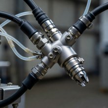
A component is not a recipe
The pictured applicator illustrates hardware detail. No nozzle size, pressure or coating compatibility can be inferred from the photograph.
Include airflow, flash-off and cure
Booth airflow removes airborne material and supports the designed operating environment, but local flow also interacts with the spray. Loaded filters, open access points or changes in part loading may alter conditions. Ventilation and hazardous-atmosphere controls require competent engineering; application trials must not bypass them to obtain a preferred finish.
Deposition also creates a film that must release volatiles, level and cure according to its chemistry. Flash-off and curing conditions belong in the validated sequence. A surface that looks smooth immediately after application may develop defects later. Record part temperature where relevant, not merely an oven setpoint, and relate the result to the coating supplier’s requirements.
Spray control becomes meaningful when it is connected to measurable acceptance criteria. Continue to finish inspection to define what the deposited film must demonstrate.